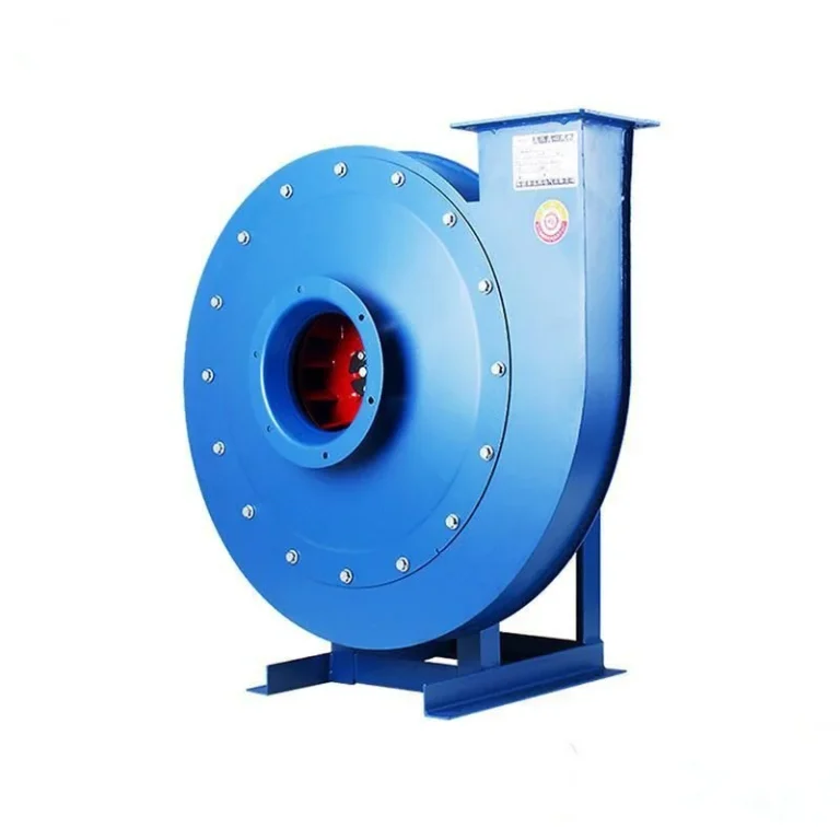
High Pressure and Low Pressure Centrifugal Fans
Pressure class decides impeller width, blade angle, casing thickness and price. How to tell which class a duty needs before a supplier picks for you.
Read More
The working principle of a centrifugal fan comes down to one idea: give air rotational speed, then slow it down in a casing that converts that speed into pressure. Everything else in the machine exists to support that exchange efficiently.
Understanding the sequence matters practically, because it explains why the fan behaves the way it does when a damper closes, why overspeed is so damaging, and why a fan that is perfectly sized on paper can still be noisy in service.
Air approaches the inlet axially and is guided by the inlet cone into the eye of the impeller, the circular opening at the centre of the wheel. The cone’s job is to accelerate the air smoothly and present it to the blades without separation. A badly designed inlet, a sharp edged flange or a starved inlet all produce turbulence here, and turbulence at the eye costs pressure that no downstream component can recover.
This is the most common installation fault in the field. A fan bolted directly to a plenum with no inlet cone, or with a flexible connector that has collapsed inward under negative pressure, will underperform its curve by 10 to 20 percent and nobody will know why.
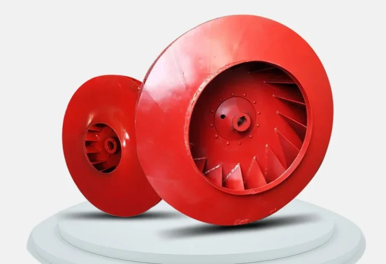
Inside the impeller the air is caught between rotating blades and forced to travel outward while spinning with the wheel. Two things happen at once. The air gains tangential velocity, because the blade is dragging it around, and it gains radial velocity, because there is nowhere to go but outward.
At the tip of the impeller the air is moving fast, often 20 to 40 m/s and sometimes more. That kinetic energy is the raw material for the pressure the fan produces. In a backward curved impeller the air leaves the blade tip at a lower absolute speed than in a forward curved one, but it does so more cleanly, which is why the backward curved form reaches higher efficiency.
The air leaves the impeller at high speed and low static pressure. It enters the volute, the spiral casing that wraps the wheel and grows in cross section as it approaches the outlet. The widening passage slows the air down, and by Bernoulli’s principle the energy that was velocity becomes static pressure.
This conversion is never perfect. Some of the kinetic energy leaves through the outlet as still-moving air, which is why total pressure includes a velocity pressure component that is wasted unless the system can use it. A typical centrifugal fan converts 60 to 80 percent of the impeller’s output into usable static pressure, the rest being lost to friction, turbulence and the residual velocity at the outlet.
Air leaves the casing perpendicular to the inlet axis, through a rectangular or circular outlet. The direction of that outlet, and which side of the casing it is on, is fixed by the fan’s rotation and discharge orientation. Turning the casing after delivery is possible on some models and not on others, which is why the discharge angle belongs on the order.
Two mechanisms, and both matter. The first is centrifugal action: air rotating inside the impeller is thrown outward and the resulting pressure gradient adds static pressure from eye to tip. The second is diffusion inside the blade passages: the passages widen from inlet to outlet, so the relative velocity of the air falls and static pressure rises even before the air reaches the casing.
Both scale with the square of tip speed. That is why pressure is so sensitive to impeller diameter and speed, and why a manufacturer cannot simply add pressure to an existing design without changing the wheel or the drive.
| Fan law | Relationship | Practical consequence |
|---|---|---|
| Flow versus speed | Q varies with N | 80% speed gives 80% airflow |
| Pressure versus speed | P varies with N squared | 80% speed gives 64% pressure |
| Power versus speed | kW varies with N cubed | 80% speed gives 51% power |
| Flow versus impeller diameter | Q varies with D cubed at constant speed | A 10% larger wheel adds about 33% airflow |
| Pressure versus air density | P varies with density | Hot air or altitude cuts pressure proportionally |
Every centrifugal fan has a curve rather than a single duty point, and the shape of that curve follows directly from the principle. At shut-off, with no flow, the impeller still spins and still generates pressure, but no air carries the energy away, so the machine sits at its maximum pressure with the air recirculating inside the casing. At free delivery, with no resistance at all, the pressure is negligible and the fan moves its maximum volume.
Between those two extremes the curve falls. A backward curved fan produces a curve that flattens and then dips slightly at high flow, which is the signature of a self-limiting design. A forward curved fan produces a curve that falls more steeply and, more importantly, a power curve that keeps rising, which is why forward curved units can overload a motor when the system resistance is lower than expected.
Reading the shape rather than a single number is what lets a buyer predict behaviour. A flat curve means the airflow stays close to design even as the filter loads. A steep curve means the airflow will fall away quickly, which is fine for a fixed system and bad for one with a filter that gets dirty.
Pressure rises with speed, but the machine has limits. The impeller is a rotating structure carrying centrifugal stress that rises with the square of tip speed, so at some point the material becomes the constraint. Standard carbon steel impellers are limited to roughly 60 to 70 m/s tip speed, aluminium to lower figures, and high strength steels to more.
The second limit is aerodynamic. As pressure rises the air is asked to diffuse more inside the blade passage, and beyond a certain point it separates from the blade surface and the flow stalls. A stalled fan loses pressure, becomes unstable and produces a distinctive low frequency rumble. This is what happens when a fan is run at very low flow against a nearly closed damper, and it is why the far left of a fan curve is not a safe operating area.
Three practical rules follow from the principle.
First, never move a fan to a different duty by changing only the motor. Changing the motor changes nothing about the airflow; changing the speed or the impeller changes everything, and both have limits set by the casing and the shaft.
Second, protect the inlet. More centrifugal fans underperform because of a starved inlet than because of a wrong selection. Straight duct into the eye, a proper cone, and no collapsed flexible connector are worth more than a better impeller.
Third, respect the right-hand side of the curve as well as the left. Running a fan far beyond its design flow drops efficiency, raises noise and, on a forward curved impeller, can overload the motor because power keeps rising with flow.
The principle is identical across the family, but the hardware changes. A high pressure centrifugal fan uses a large diameter impeller with narrow, closely spaced blades to convert speed into pressure at 1,919 to 9,149 Pa. A double inlet unit feeds two eyes from opposite sides of a wide impeller to move high volume at modest pressure.
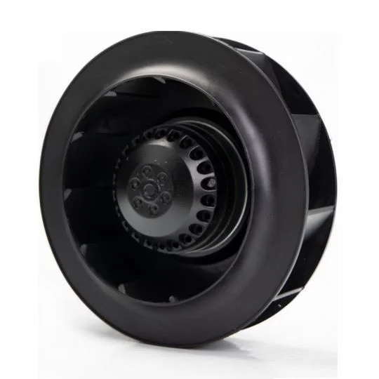
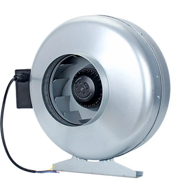
At the small end, a circular duct centrifugal fan applies the same principle in a 100 to 315 mm housing, producing 68 to 451 Pa from a 60 to 225 W motor. The physics does not change with size; only the numbers do.
Air is drawn into the centre of a spinning wheel, thrown outward by the blades, and collected by a spiral casing that slows it down and turns the speed into pressure. The air then leaves at right angles to the inlet.
It converts shaft power into air pressure in two steps: centrifugal force in the rotating impeller raises pressure from eye to tip, and diffusion in the widening blade passages and volute casing converts velocity into static pressure.
Because the fan can only deliver the energy the motor supplies. If the system resists more, the fan moves less air at higher pressure. That trade is the fan curve, and the operating point is where the curve meets the system resistance.
Yes. Below roughly 30 percent of design flow the impeller can stall, producing vibration, noise and unstable pressure. Systems that need to run at very low flow should use a variable speed drive rather than a damper.
A loaded filter moves the operating point to lower flow and higher pressure, which shifts the fan towards the left of its curve where flow separation and turbulence increase. Noise usually rises before airflow drops enough to notice.