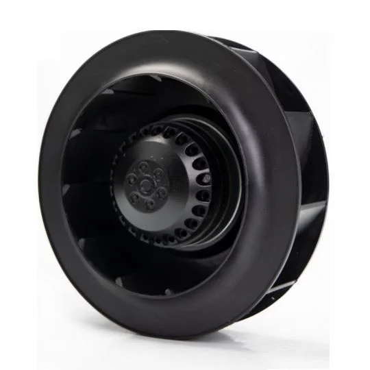
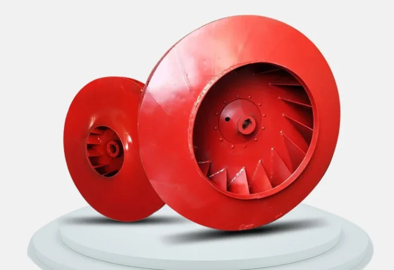
Centrifugal Fan CFM: How to Work Out the Airflow You Need
Published: Author: wilmall
CFM is the number buyers ask for first and understand last. A centrifugal fan does not have a CFM. A centrifugal fan has a curve, and the CFM it delivers depends entirely on how much resistance the system puts in front of it. The job of sizing is to find the point where the fan’s curve crosses the system’s resistance curve, and then confirm that point is where you wanted to operate.
This page walks through that process in the order it should be done: establish the CFM the application actually needs, calculate the resistance, find the intersection, then check the result is not sitting on a bad part of the curve.
Step one: work out the CFM the application needs
There are three common starting points, and each has a formula worth knowing.
Air changes per hour. For room ventilation, CFM equals room volume in cubic feet multiplied by air changes per hour, divided by 60. A 10 m by 8 m by 3 m workshop is 240 m3, or about 8,475 cubic feet. At 6 air changes per hour that is 848 CFM. This is the correct method for general ventilation, and the air change rate should come from the applicable standard or from the process, not from habit.
Heat removal. CFM equals 3.16 times the heat load in watts divided by the allowable temperature rise in degrees Celsius, when working in metric, or CFM equals 1.08 times BTU per hour divided by the temperature rise in Fahrenheit. A cabinet dissipating 1,500 W with a 10 degree rise needs about 474 CFM in metric terms. This is the method for enclosure cooling and for anything where the air is carrying heat away.
Capture velocity. For extraction, the CFM must be enough to hold a capture velocity at the hood face. Welding fume needs roughly 100 to 200 feet per minute at the arc, grinding dust rather more, and the required CFM then depends on hood geometry and distance. This is the method that gets underestimated most often, because a hood 300 mm further from the work can double the airflow needed.
Step two: convert resistance into static pressure
Every component in the system costs pressure. Straight duct costs a little per metre, elbows and transitions cost a fixed amount each, and filters, coils, dampers and hoods cost whatever the manufacturer says. Add them up and you have the total static pressure the fan must overcome at the design CFM.
Component
Typical pressure loss
Note
Straight galvanised duct
0.8 to 1.2 Pa per metre at 5 m/s
Rises with the square of velocity
90 degree elbow
15 to 40 Pa each
Hard bends cost several times a swept bend
Bag filter, clean
400 to 800 Pa
Design to the dirty figure, not the clean one
Bag filter, dirty
1,200 to 2,000 Pa
The number that matters for fan selection
Cooling or heating coil
80 to 250 Pa
Wet coils cost more than dry
Fire damper
20 to 50 Pa
Easy to forget
Supply or exhaust louvre
30 to 80 Pa
Face velocity dependent
Kitchen grease filter bank
150 to 350 Pa
Rises quickly as it loads
The single most common sizing error in industrial ventilation is designing to the clean filter pressure. A system sized at 600 Pa of filter loss will deliver its design CFM for perhaps three weeks, then fall away as the bags load, and the fan will sit at a duty point nobody planned for.
A worked example
Take a welding bay that needs 2,000 m3/h at the extraction hood. Twelve metres of duct at 1.0 Pa per metre is 12 Pa. Three elbows at 30 Pa each is 90 Pa. A cartridge filter at 700 Pa dirty, a louvre at 50 Pa, and a balancing damper at 40 Pa. Total system resistance is about 892 Pa, so the fan has to be selected at 2,000 m3/h and 900 Pa, not at 2,000 m3/h free air.
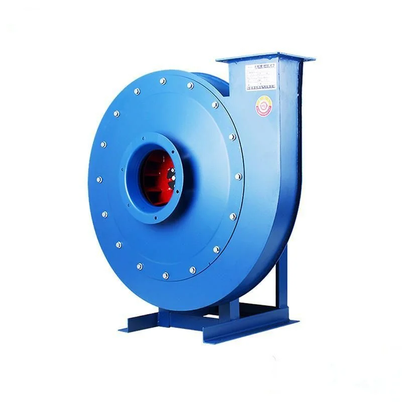
Looking at our centrifugal exhaust range, that duty sits comfortably inside the larger machine numbers, while the same airflow at 900 Pa would be near the top of the smaller duct units and would leave no margin for a loaded filter. This is the moment where an undersized fan gets ordered: the airflow matches, the pressure does not, and the mistake only shows up once the filter starts to load.
Each row is a duty point. Selecting on airflow alone ignores the pressure column entirely.
Step three: find the intersection
Plot the centrifugal fan curve and the system curve. The fan curve falls as flow rises; the system curve rises as flow rises. Where they cross is the operating point. If that point is at 3,200 CFM when the design needed 3,000, the centrifugal fan is slightly oversized and will run a little faster and noisier than planned. If it lands at 2,600, the system will not meet its duty and the usual response, opening a damper, only makes it worse.
Our published curves for the high pressure centrifugal fan show this clearly: the 4A machine number delivers 824 to 1,264 m3/h at 3,584 to 3,597 Pa, and the same casing with a larger motor reaches 1,410 to 1,704 m3/h at a lower pressure of 3,507 to 3,253 Pa. Read those two lines together and the trade is visible in a single row of the table.
A performance table is a fan curve in rows. Each model number covers a range of airflow at a falling pressure.
Step four: check the operating point is sensible
A duty point that lands technically on the curve can still be a bad choice. Four checks catch most of the problems.
Not too far left. Below about 30 percent of peak flow the centrifugal fan runs into surge or stall, with noise and vibration. Small fans running against a nearly closed damper are the classic case.
Not too far right. Beyond peak flow efficiency falls away sharply and, on forward curved impellers, motor power keeps climbing.
Not at peak efficiency alone. Design slightly to the right of peak efficiency if the system resistance will rise over time, so the fan drifts towards the best point rather than away from it.
Motor margin. Absorbed power at the duty point should be no more than about 85 to 90 percent of motor rating, leaving room for a slightly open system and for voltage variation.
Converting between CFM and m3/h, once and for all
One cubic metre per hour is 0.5886 CFM. One CFM is 1.699 m3/h. The quick mental versions: multiply m3/h by 0.59 to get CFM, or multiply CFM by 1.7 to get m3/h. A 1,000 m3/h centrifugal fan is a 589 CFM centrifugal fan. A 1,000 CFM unit is a 1,699 m3/h unit.
Pressure converts as 1 inch of water gauge equals 249 Pa, and 1 mm of water equals 9.81 Pa. A specification written in inches of water and answered in pascals is the most common source of a 4 times error in a fan order, and it happens because nobody converted before comparing.
What happens to CFM when you change speed
Flow changes in direct proportion to speed. Run a fan at 80 percent speed and it delivers 80 percent of the CFM, at 64 percent of the pressure, using 51 percent of the power. That cube relationship is why variable speed control is the single largest energy saving available in fan systems, and why an oversized fan with a drive can beat a correctly sized fan without one.
Speed control changes CFM linearly and power cubically, which is why an EC fan so often wins on running cost.
Airflow also changes with air density, which falls with altitude and rises with temperature. A centrifugal fan selected at sea level and installed at 1,500 m delivers about 15 percent less mass flow for the same volume, and a centrifugal fan moving 300 degree air needs correction before the catalogue curve means anything. Volume flow stays roughly constant with temperature, but pressure and power both fall in proportion to density.
Frequently asked questions
How do I calculate CFM from a centrifugal fan’s rated airflow?
You cannot, without the pressure. A rated figure is only valid at the resistance stated in the catalogue. Convert m3/h to CFM by multiplying by 0.5886, then confirm the resulting CFM is quoted at the static pressure your system actually has.
What is a good CFM for a workshop?
It depends on the air change rate the process needs. General workshop ventilation is often designed at 6 to 10 air changes per hour, which for a 240 m3 space means 850 to 1,400 CFM. Welding or solvent work needs local extraction sized on capture velocity instead, which usually exceeds the general ventilation figure.
Does a bigger fan always move more CFM?
At the same speed and pressure, yes, roughly in proportion to impeller diameter squared for a given width. But a larger fan at lower speed can move the same CFM more quietly and efficiently, which is why large slow fans are used wherever noise matters.
Why does my centrifugal fan deliver less CFM than the catalogue says?
Usually because the system resistance is higher than assumed, the inlet is restricted, the discharge is undersized, or the air density is lower than at the test conditions. Check the actual static pressure at the fan inlet and outlet before blaming the fan.
Can I reduce CFM without a variable frequency drive?
Yes, with an inlet damper or a discharge damper, but both waste energy: the fan still spins at full speed and absorbs nearly the same power. A damper reduces flow by adding resistance, not by reducing work, which is why drives pay for themselves so quickly.
Nine checks that separate a fan that runs for fifteen years from one that fails in a season, plus what big-box listings never tell you about duty points.
Forward curved, backward curved, radial and aerofoil impellers behave very differently. A practical breakdown of centrifugal fan types and how to pick one.